

Dropbox needs its underlying network infrastructure to be reliable, high-performing, cost-effective, and truly scalable. In previous posts we described how the edge network was designed to improve user performance, and how the supporting multi-terabit backbone network spans continents to interconnect edge PoPs and multiple data centers.
In this post we describe how we evolved the Dropbox data center network from the legacy chassis based four-post architecture to a scalable multi-tier, quad-plane fabric. Also, we successfully deployed our first fabric at our newest data center in California earlier this year!
Dropbox network physical footprint
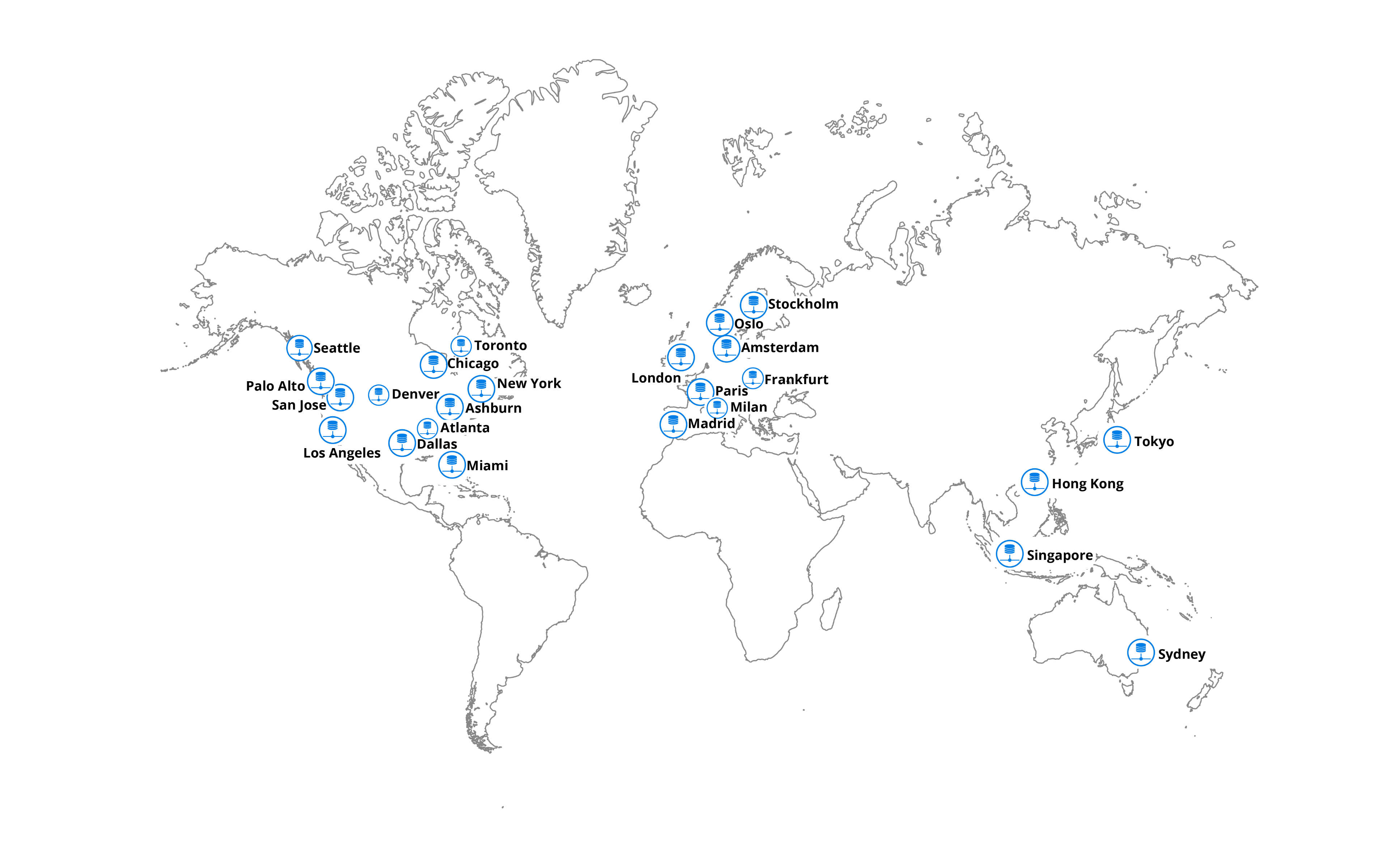
We currently have global network presence and multiple data centers in California, Texas and Virginia. From a redundancy perspective, the North American continent is carved into regions—East, Central, and West—thereby having a distributed data center approach and improving resiliency in events of failure.
Legacy four-post architecture
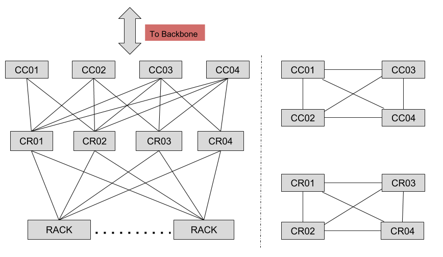
A cluster is comprised of ‘n’ rack switches and four supporting CR devices in a tier, and each CR device is a chassis based system. The cluster router (CR) tier handles inter-rack traffic within the cluster and traffic entering or leaving the cluster. Typically, a data center is comprised of more than one cluster, and interconnection between clusters is done via the cluster connector (CC) tier, itself comprised of four CC devices (see figure #2). The cluster connector (CC) tier handles inter-cluster traffic within the datacenter and is the entry/exit point for all traffic at a datacenter. We used 100G connectivity across all the links seen in the above figure.
From a protocol perspective, we run eBGP between the cluster connector (CC) and cluster router (CR) tiers using private autonomous system numbers (ASN) numbers. In contrast, between a rack and cluster router (CR) we use iBGP and route-reflectors to propagate routing information within the cluster. Additionally, devices within the CC and CR tiers are fully meshed using ISIS as the IGP and peering via iBGP using loopback interfaces.
Scaling limitations and growth
As we kept adding megawatts of data center space to support growth, we quickly realized that the older four-post architecture wouldn’t be able to scale to meet our future needs. The port density on the chassis based units directly translated to the number of racks a cluster could support, making network infrastructure a limiting factor. Adding new clusters to an existing data center or upgrading cluster-uplink capacity meant having unused ports on the upstream aggregating CC-tier. Also, troubleshooting a traffic-related issue within a system using multiple line cards and supporting fabric modules could quickly become complex and time consuming.
Keeping in mind the challenges with the older design, we wanted to ensure our next generation design solved them while remaining future-proof.
Below are design considerations we focussed upon while engineering the fabric:
- Achieving a rack count greater than that offered by the legacy design
- Ability to scale horizontally while adding capacity on demand
- Non-blocking fabric with increased redundancy
- Chassis-free design
- Utilizing an identical ASIC at every tier
- All fabric links/interconnects utilize 100G connectivity
- Multiple ECMP options at every layer
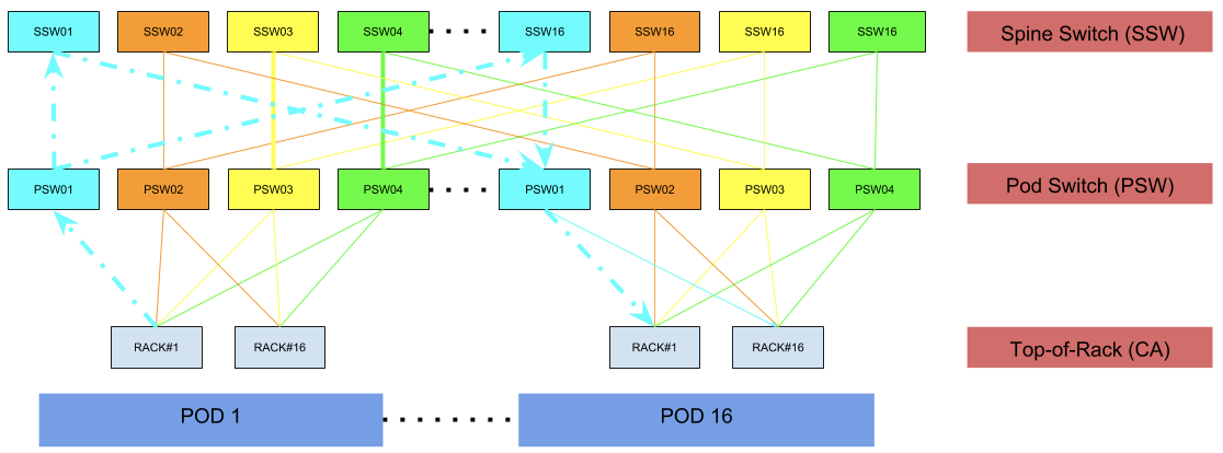
Quad-plane, 3-tier fabric:
- 16 racks per pod
- 16 pods per fabric
- 64 spine switches
- 4 pod switches per pod
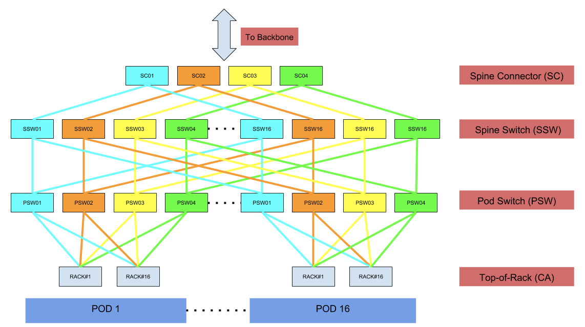
As seen above in figure #3, the spine connectors (SC) and spine switches (SSW) are the building blocks of the fabric, and the pod switches (PSW) can be added incrementally on-demand, allowing the design to be elegantly scaled horizontally. Each device above, including the rack switch, is using an identical ASIC that offers 3.2 Tbps of switching capacity (32 ports of 100G), with super-low latency, and has a single rack-unit footprint, while leveraging merchant silicon. Our latest deployment includes 16 pods, however this can be further scaled to support 31 pods thereby accommodating close to 500 racks. The number of pods in the fabric is dictated by the number of ports reserved on each spine switch (SSW) device. Based on our traffic patterns, we initially reserved fewer ports for upstream connectivity responsible for traffic entering and leaving the fabric. While accommodating for future growth, we can always increase the upstream capacity and appropriately scale the number of pods in the fabric.
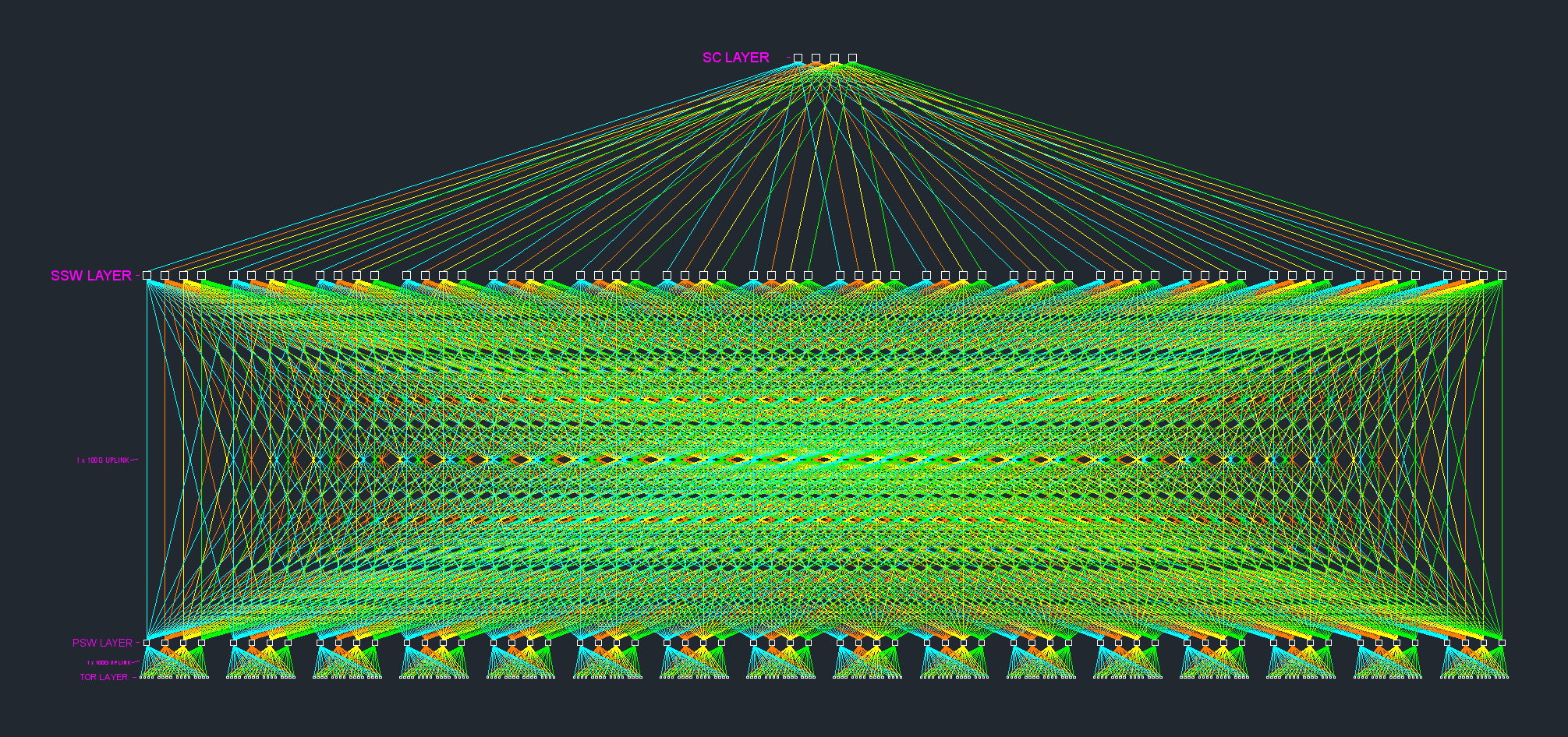
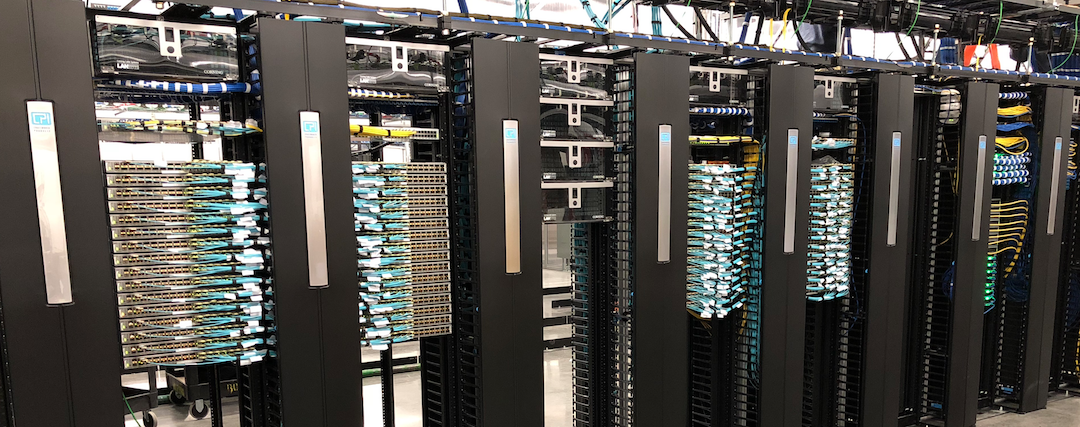
Cabling and optics
As seen in figure #4 below, the new design resulted in a few thousand interconnections across the building blocks of the fabric itself, not accounting for the rack uplinks! Based on our physical layout these distances were within the operating limits of a QSFP-100G-SR4 optic. Hence, we deployed QSPF-100G-SR4 in a combination with MPO connectors over multimode fiber (MMF). The longest cable in the physical layout was roughly 140 feet, which spanned from the main distribution frame (MDF) to our farthest cabinet location (again within the operating limits of a QSFP-100G-SR4 optic).
Physical design and layout
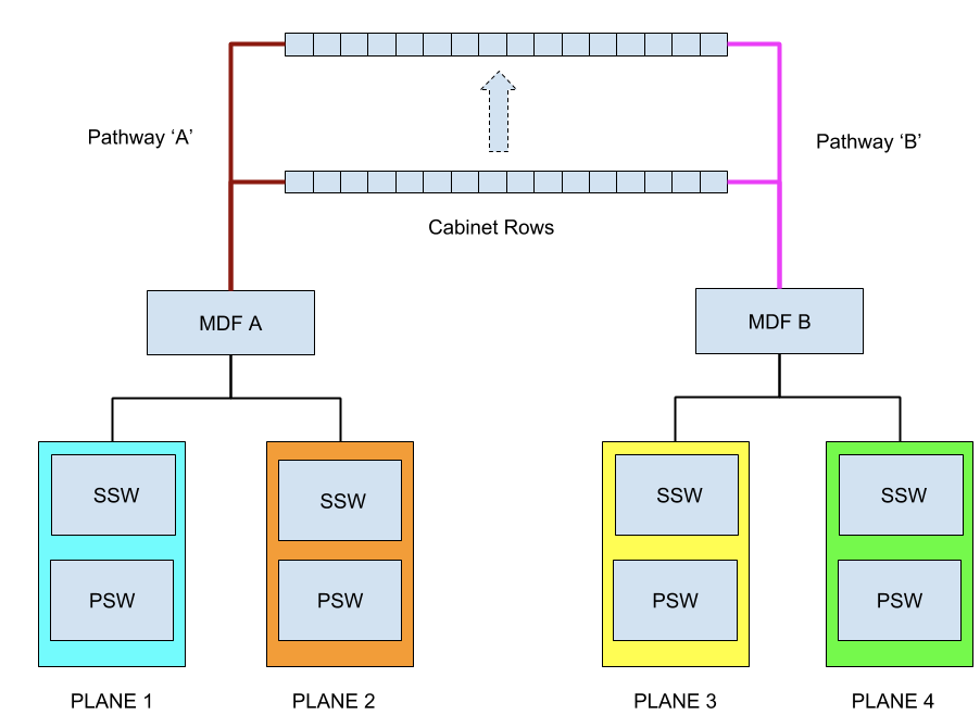
In addition to logical network failure domains, we decided to separate the planes across the two main distribution frame (MDF) rows, in our case MDF ‘A’ and MDF ‘B’ to add physical diversity.
Simultaneously, this allowed us to increase our failure domain when dealing with electrical anomalies as each MDF row is supported by redundant electrical power distribution panels. Furthermore, each MDF row has diverse network pathways to each cabinet position.
Why quad-plane?
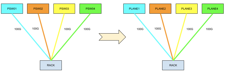
Our idea of a “plane" reflects an independent failure domain. Based on our needs, each rack switch connecting to the fabric is offered 4X100G of uplink capacity, hence the term ‘quad-plane’. At any given time, we should be able to lose an entire plane’s worth of capacity and still remain healthy, this would mean losing one spine connector (SC), 16 spine switches (SSW) and 16 pod switches (PSW) identically colored.
Non-blocking and oversubscription
Non-blocking means that the number of inputs equals the number of outputs. It wasn’t a pre-requisite, but we preferred to utilize the fabric to its fullest potential starting on day one, and hence we constructed a non-blocking network with a 1:1 oversubscription ratio between any two racks within the fabric. This also helped us steer away from any potential speed mismatch related issues and simplified cabling by not needing to split a 100G port.
Colors and routing within the fabric
Every device and interconnect within the fabric is uniquely colored. Each color signifies a unique plane. A plane within the fabric is responsible for 25% of overall rack throughput. This further explains why no two different color devices are connected. Once a packet traverses a uniquely colored link or device, it will only further traverse identically colored links or devices. This applies to all traffic whether intra-fabric i.e rack-to-rack traffic or traffic exiting the fabric destined to networks external to the fabric, this is further illustrated in figure #8 and figure #9 respectively.
Intra-fabric packet traversal:
Networks external to fabric:
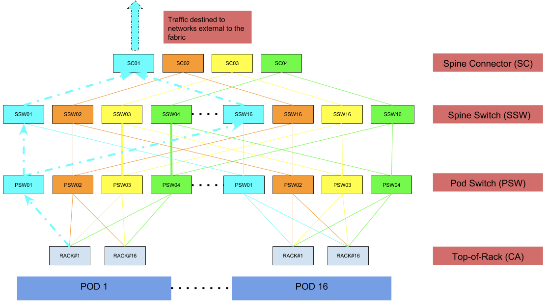
We built the fabric entirely on BGP, specifically running eBGP between any two devices. As compared to using iBGP and route-reflectors in the legacy design, eBGP helped us keep things simple and offers deeper visibility into a routing-prefix while leveraging AS-Path information. As in our older designs, the fabric is also a pure Layer 3 network down to the rack switch, offering support for IPv4 and IPv6. The fabric relies on equal-cost multi-path routing (ECMP) & per-flow hashing resulting in equal distribution of flows equally across available links.
Failure domain analysis
Pod switch (PSW):

- Traffic profile: Handles both east↔west and north↔south flows
- If a PSW fails, all the rack switches in the pod lose upstream capacity by 25%, basically a failure domain of 75%
- This provides better fault isolation and reduces the impact to only a single pod, compared to the existing four-post design where all racks would lose upstream capacity by 25%
Spine switch (SSW):
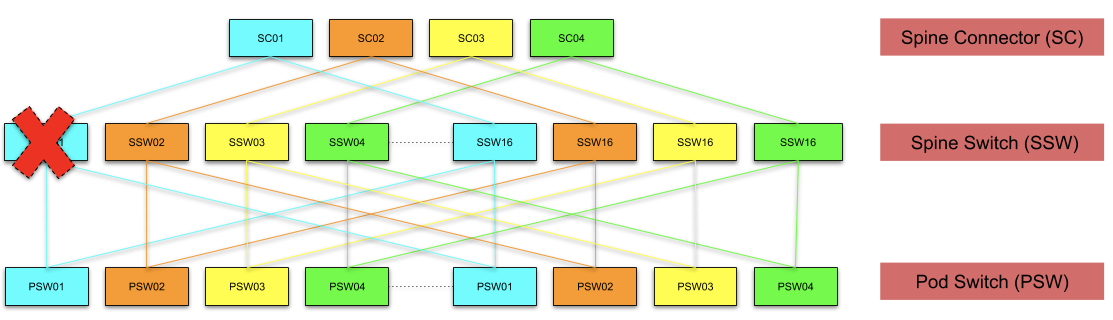
- Traffic profile: Handles both east↔west and north↔south flows
- A spine switch (SSW) connects to 16 pod switches (PSW) and four spine connectors (SC). Losing a node out of 16 devices in a plane results in a failure domain of 93.75% which is really low as compared to a node failure in the four-post design wherein all racks in the cluster would lose upstream capacity by 25%
Spine connector (SC):
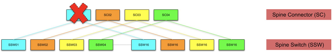
- Traffic profile: Handles only north↔south flows
- A spine connector tier is comprised of four devices. Failure of a single device results in 25% loss of north↔south capacity resulting in a failure domain of 75%
- However, this failure only impacts flows entering/leaving the fabric. East↔west flows remain un-impacted!
Future scaling
The existing fabric design can scale close to 500 racks while operating in a non-blocking fashion. Making use of an ASIC that offers higher port density, say 64X100G, the existing fabric design can be scaled to support 4x the rack capacity, again non-blocking! As merchant silicon continues to evolve and produce denser chips, having much denser fabrics is very well a possibility. To accommodate relatively higher rack counts, a fabric may span multiple physical suites and outgrow the maximum supported distance on a QSFP-100G-SR4 optic which would require the need to explore potential transceivers: Parallel single mode 4-channel (PSM4) or coarse wavelength division multiplexing four-lane (CWDM4) or any future specifications to achieve connectivity across a fabric spanning physically separated facilities.
We’re hiring!
The Network Engineering team is hiring talented Network Engineers with a desire to build and solve problems at scale across Backbone, Datacenter, Edge, Optical, and much more. You’ll be a part of a small team that has a huge impact on the world. We’re also hiring for a wide variety of engineering positions in San Francisco, New York, Seattle, Tel Aviv, and other offices around the world
Acknowledgements
Implementing the new design would not have been possible without tightly-coupled collaborative efforts across the organization involving network engineering, network reliability engineering, cluster operations, supply chain, datacenter operations, finance, and technical program managers. A huge shoutout to all involved in making this effort a success!


